


Views: 0 Author: Site Editor Publish Time: 2026-10-06 Origin: Site


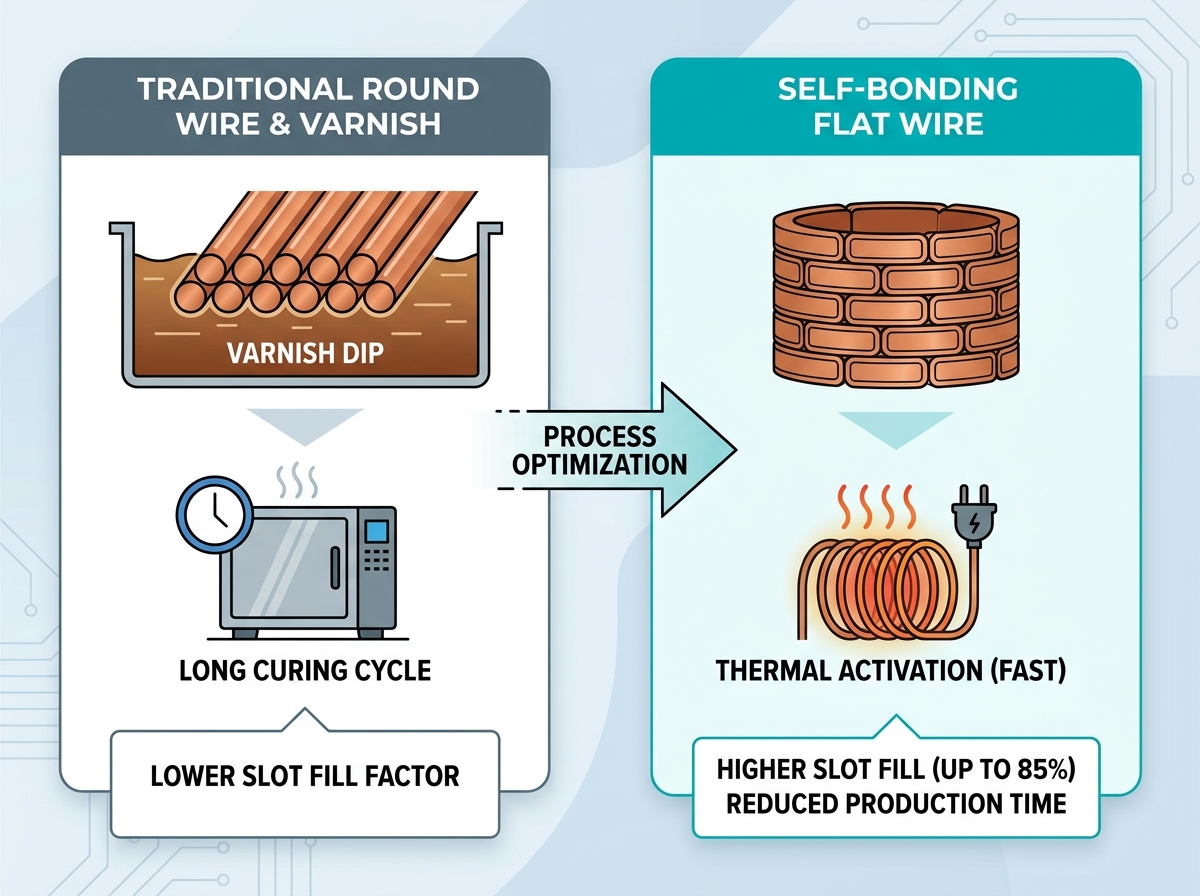
Shifting from round wire and secondary varnishing to flat profiles fundamentally transforms motor and transformer design. Manufacturers increasingly rely on these advanced materials. You can maximize the slot fill factor and drastically reduce production cycle times.
However, specifying flat wire is rarely straightforward. It requires strict control over aspect ratios, corner radii, and thermal classes. A mismatched bonding layer or base enamel inevitably leads to coil failure. You might face destructive delamination or serious production bottlenecks.
This article provides engineers and procurement teams with an evidence-based framework. We will explore how to thoroughly evaluate, correctly specify, and rigorously test self bonding enameled flat wire for automated or semi-automated winding applications. You will learn how to navigate vendor specifications and implement reliable winding processes.
Replacing secondary impregnation with self-bonding wire cuts curing times but demands precise thermal or solvent activation controls.
Achieving a high slot fill factor (up to 80-85%) relies on specifying exact corner radii and managing flat wire aspect ratios.
Selecting the correct base coat (e.g., polyurethane, polyester-imide, or polyvinyl acetal) dictates the wire's mechanical toughness and chemical resistance.
Supplier qualification must include standardized peel strength and dielectric breakdown testing under actual production winding tensions.
Engineers must carefully evaluate the trade-off between higher upfront material costs and reduced manufacturing overhead. Switching to self-bonding options eliminates the need for vacuum pressure impregnation (VPI). You can remove curing ovens from the factory floor entirely. This transition also eliminates volatile organic compound (VOC) emissions associated with traditional varnishes. The resulting streamlined process accelerates throughput and lowers facility ventilation requirements.
Comparing the cross-sectional geometry of flat wire against round wire reveals massive advantages. Round wire inherently leaves empty spaces between conductors. Flat wire stacks neatly and reduces this interstitial void space. Designers routinely push the slot fill factor up to 80% or 85%. This density directly impacts motor power density. It also significantly boosts transformer efficiency while keeping the footprint compact.
Continuous bonding layers also improve dimensional stability. When you apply conventional liquid resins, uneven distribution often occurs. A pre-applied bonding layer melts and solidifies uniformly across the coil. This uniformity proves critical for manufacturing coreless coils. It is equally important when producing tight-tolerance stators for high-performance applications. The cured coil retains its exact engineered dimensions under mechanical stress.
Successful coil design begins with selecting the appropriate base insulation. The underlying enamel dictates thermal endurance and mechanical strength. We must match these properties to the end-use environment.
Consider these primary base insulation options:
Polyvinyl acetal: Specify polyvinyl acetal enameled flat wire for applications requiring high mechanical toughness. It provides excellent resistance to transformer oils.
Polyurethane (Class 130-155): Choose this formulation for high-speed production. It enables direct solderability without prior mechanical stripping.
Polyester-imide / Polyamide-imide (Class 180-220): Deploy these rugged materials for high-temperature EV traction motors. They easily handle heavy-duty industrial applications.
Next, engineers must determine the bonding layer activation method. Thermal activation relies on oven baking or Joule heating (passing current through the wire). You must map the exact activation temperature against the thermal mass of the coil. If the core absorbs too much heat, the outer layers may not bond.
Alternatively, solvent activation uses alcohol or acetone during winding. It limits thermal stress on sensitive components. However, this method introduces VOCs back into the process. You will need carefully controlled factory ventilation to maintain safety.
Vendor datasheets sometimes use varying industry terms. "Bondable magnet wire" is a widely used description. Another common term is self adhesive magnet wire. These are functionally identical. Always check whether the supplier bases their testing on NEMA MW 1000 or IEC 60317 standards to ensure compliance.
Enamel Type | Thermal Class | Key Advantage | Common Application |
|---|---|---|---|
Polyvinyl Acetal | 105 - 120 | High mechanical toughness, oil resistance | Oil-filled transformers |
Polyurethane | 130 - 155 | Direct solderability without stripping | Small relays, audio coils |
Polyester-imide | 180 - 200 | High thermal endurance | Industrial motors |
Polyamide-imide | 200 - 220 | Exceptional chemical and heat resistance | EV traction motors |
Establishing acceptable width-to-thickness limits remains crucial for winding success. We refer to this as the aspect ratio. High aspect ratios increase the risk of a phenomenon called "keystoning." During edge bending, the rectangular shape deforms into a trapezoid. This deformation compromises the insulation and wreaks havoc on slot fill calculations.
Corner radii requirements represent another vital specification. Many engineers overlook this detail when requesting quotes. Sharp corners cause severe manufacturing issues. Surface tension pulls liquid enamel away from sharp edges during production. This phenomenon causes enamel thinning and inevitable dielectric failure in the final coil.
To avoid these failures, you must specify corner radii based on conductor thickness. Refer to standard IEC or NEMA radius tables. Following these industry guidelines ensures a uniform insulation build across the entire profile.
You must also define acceptable plus or minus variances. Tight tolerance standards apply to both the bare copper dimensions and the overall insulation diameter. Wide variations quickly lead to slot jamming during automated insertion. If the wire runs too large, equipment damages the bonding layer. If it runs too small, the coil vibrates loose during operation.
Bringing self-bonding material into production introduces specific mechanical challenges. Flat profiles remain highly sensitive to tension variation. Over-tensioning causes immediate copper elongation. This stretching alters the cross-section permanently. Consequently, the electrical resistance of the coil increases beyond acceptable design limits. We recommend upgrading to precise hysteresis tensioners to prevent erratic pulling.
Insulation damage during bending is a persistent threat. Micro-cracking often occurs on the outer radius of edge-wound coils. You must carefully address this risk before mass production begins. We require rigorous verification of the base enamel's flexibility. Bending mandrels must respect the minimum bend radius defined by the wire manufacturer.
Engineers must also account for springback factors. Calculating the difference between the winding mandrel dimensions and the final cured coil prevents fitment issues. The bonding layer certainly mitigates some springback once activated. However, the baseline mechanical limits of the copper still remain. You should expect to iteratively adjust tooling dimensions during initial trials.
Finally, monitor activation uniformity diligently. Joule heating carries the specific risk of generating "cold spots." The inner layers might bond perfectly while outer layers fail to reach the necessary activation temperature. Use thermal imaging cameras during prototype runs. Adjust the current profile until the entire coil mass reaches a uniform state.
Procurement teams need a robust framework for evaluating potential partners. When shortlisting vendors, prioritize those capable of custom-drawing flat copper wire. Avoid suppliers who merely flatten round wire through rollers. Custom drawing operations provide vastly superior dimensional consistency and better grain structure. This distinction becomes obvious during tight-radius bending.
Demand certified test reports before accepting any material. Reliable suppliers willingly provide documentation for breakdown voltage at both room temperature and peak operating temperature. You also need bond strength data, specifically peel and shear testing results. Thermal endurance certificates ensure the enamel withstands your intended lifecycle.
Once you select a qualified vendor, follow structured prototyping next steps:
Request manageable samples: Order 5 to 10 kg sample spools. This provides enough material for meaningful testing without excessive cost.
Run realistic winding trials: Use production-equivalent tooling and tensioners. Do not rely on manual hand-winding for validation.
Conduct destructive inspection: Perform cross-sectional potting. Use microscopic inspection to verify enamel integrity and confirm complete bonding layer coalescence.
Transitioning to self-bonding rectangular profiles requires a disciplined evaluation framework. You must carefully balance thermal class requirements against your preferred activation methods. Success relies entirely on demanding precise dimensional tolerances from your chosen suppliers. Pay special attention to corner radii and aspect ratios to avoid dielectric failures.
Your action-oriented next step involves the factory floor. Begin with a comprehensive audit of your existing winding equipment capabilities. Evaluate your tensioners and heating power supplies thoroughly. Upgrading obsolete winding machinery is often necessary before requesting advanced vendor specifications. Taking this proactive step guarantees a smoother, more profitable production launch.
A: Generally 6 to 12 months under controlled temperature and humidity. Keep storage environments below 30°C and less than 70% relative humidity. The bonding layer can degrade or pre-activate if you store it improperly. Always practice strict first-in, first-out inventory management.
A: Yes, for most applications, provided you select the correct topcoat and fully cure it. The coalesced bond offers excellent structural integrity. However, for extreme high-vibration environments, you may still require secondary potting or encapsulation to guarantee performance.
A: Flat wire insulation builds are categorized similarly, such as Grade 1 or Grade 2. However, they require special attention at the corner radii. The build tends to thin out at these edges due to surface tension during manufacturing.
A: It is generally less effective for large cross-sections. Solvent struggles to penetrate deeply into massive coils. Thermal activation, such as resistance or oven heating, is preferred for thick profiles. Heat ensures deep, uniform penetration of the activation energy.


