Views: 0 Author: Site Editor Publish Time: 2026-09-16 Origin: Site
Aluminum magnet wire offers undeniable commercial appeal for modern electrical designs. It delivers substantial weight reduction and cost stability compared to traditional heavy metals. These benefits make it an attractive option for large-scale manufacturing.
However, engineering teams frequently encounter technical trade-offs regarding electrical performance. Unanticipated spikes in resistance can easily trigger thermal runaway. This reduces overall motor efficiency and causes premature field failures in critical applications. We must address these variations to protect product reliability.
This article isolates the physical, mechanical, and manufacturing root causes of excessive resistance in aluminum windings. You will learn evidence-based mitigation strategies designed to solve these exact issues. We provide clear guidance for engineering and procurement teams to ensure consistent performance.
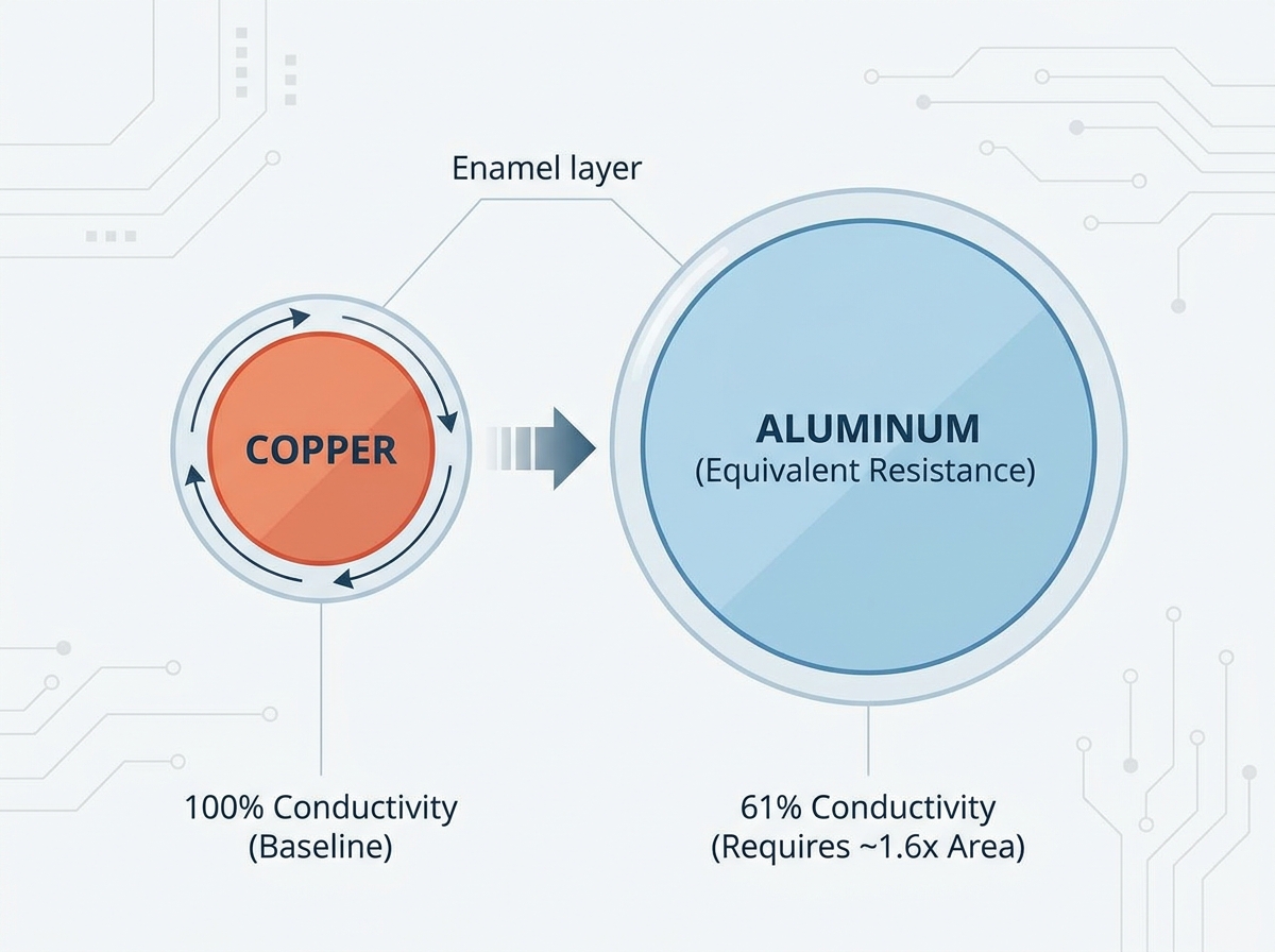
Baseline material physics dictate that aluminum has only 61% the volumetric conductivity of copper, requiring strict equivalent-gauge recalculations.
Excessive resistance spikes are rarely due to the bulk material; they are typically caused by galvanic corrosion, improper enamel stripping, or micro-fractures during winding.
Termination methodology (e.g., ultrasonic welding, specialized crimping with oxide-inhibiting compounds) is the most critical variable in stabilizing motor winding conductor resistance.
Standardizing quality control (QC) protocols using micro-ohm meters and thermal cycling tests prevents latent resistance issues from reaching the field.
Engineers must first differentiate expected material limitations from true manufacturing defects. Not all resistance indicates a failure. Sometimes, it merely reflects baseline physics.
Standard electrical grade aluminum (EC grade) behaves differently than copper. It has only 61% the volumetric conductivity of copper. The "61% Rule" dictates design parameters strictly. To achieve an identical DC resistance, aluminum requires a cross-sectional area roughly 1.6 times larger than copper. If you merely swap materials size-for-size, baseline resistance naturally increases. You must intentionally design around aluminum magnet wire resistance to ensure proper functionality.
Temperature increases also affect aluminum disproportionately inside confined stator slots. All metals increase in resistance as they heat up. However, aluminum windings experience severe thermal coefficient factors. When pushed hard, internal slot temperatures rise rapidly. This causes the resistance to climb faster than a standard copper baseline. You must account for this exponential thermal penalty during the initial design phase.
High-frequency applications amplify these challenges further. Inverter-driven motors operate at high switching frequencies. This introduces severe skin and proximity effects. Alternating current pushes to the outer edge of the conductor. This artificially shrinks the usable cross-section. Because aluminum already requires a larger diameter, these AC resistance spikes become highly problematic. Precise strand sizing and geometric planning become mandatory to control losses.
Property | Copper Baseline | EC Grade Aluminum |
|---|---|---|
Volumetric Conductivity | 100% (IACS) | ~61% (IACS) |
Cross-Sectional Requirement | 1.0x (Standard) | ~1.6x (Equivalent) |
Thermal Conductivity | ~385 W/(m·K) | ~205 W/(m·K) |
Even perfectly designed coils can fail on the production line. Manufacturing variables often introduce severe implementation risks. Unplanned spikes generally stem from four hidden mechanical causes.
Incomplete Enamel Stripping: Modern insulation uses robust polymers. Leftover polyamide-imide or polyurethane acts as a dielectric barrier. If mechanical or chemical stripping leaves even a microscopic film, resistance jumps at the connection point. You must remove this enamel entirely to establish a clean metal-to-metal bond.
Rapid Surface Oxidation: Aluminum is highly reactive. It forms a dense aluminum oxide layer within seconds of atmospheric exposure. This oxide layer is an excellent electrical insulator. It behaves like a ceramic barrier. If you join wires over this layer, current cannot flow freely. You must actively break or displace this oxide during termination.
Work Hardening and Cross-Section Reduction: Automated winding machines often exert too much tension. Over-tensioning pulls the wire past its yield strength. This causes localized necking, where the wire physically thins out. A reduced cross-section artificially inflates resistance per meter. Tension control must remain ultra-precise for softer metals.
Galvanic Corrosion at Terminations: Terminations often involve dissimilar metals. Engineers frequently join aluminum to copper leads or brass terminals. In humid environments, this creates a galvanic cell. The aluminum acts as an anode and sacrifices itself. Bi-metallic degradation slowly eats away the joint. This steadily increases localized resistance over time until failure occurs.
Common Mistake: Relying on standard copper winding tension parameters when running aluminum wire. You will almost certainly cause necking and inflate baseline resistance.
Termination methodology is your most critical production variable. Poor connections ruin perfectly wound coils. You must carefully evaluate solution categories to stabilize motor winding conductor resistance. Every technique carries unique tradeoffs regarding capital expense and long-term reliability.
Ultrasonic welding represents the highest tier of termination quality. High-frequency vibrations scrub the metals together under pressure. This process breaks through the stubborn oxide layer natively. It physically merges the atomic structures of the metals. Evaluation shows high initial equipment CapEx. However, it delivers the lowest long-term resistance variance in the field. It entirely eliminates the need for messy flux or mechanical stripping.
Insulation Piercing Connectors (IDCs) and crimp terminals offer a different approach. These components utilize serrated internal barrels. The sharp teeth bite through the enamel and the oxide layer simultaneously. You must use oxide-inhibiting compounds (dielectric grease) inside these terminals. This prevents oxygen from reaching the freshly exposed metal. Evaluation indicates lower CapEx than welding. However, it requires stringent tooling calibration. If you crush the wire, you reduce the cross-section. If you crimp too loosely, you invite corrosion.
Brazing or soldering requires specialized fluxes specifically formulated for aluminum. Standard copper fluxes will fail entirely. The specialized flux chemically eats the oxide layer. Evaluation shows this method is highly technique-dependent. It requires skilled operators. Furthermore, flux residue is inherently corrosive. If workers do not clean the joint perfectly, long-term chemical degradation will occur. This hidden corrosion slowly inflates connection resistance.
Best Practice: Implement an automated dispense system for oxide-inhibiting grease when using crimp terminals to eliminate operator variance.
Transitioning base metals requires systemic engineering changes. You cannot treat aluminum as a simple drop-in replacement. We must adopt a features-to-outcomes framework to manage new physical constraints.
Slot Fill Ratios: Aluminum demands larger gauges. Stator or transformer bobbin geometry must accommodate this extra bulk. You must adjust the winding windows without compromising the core's structural integrity. If you force too much wire into a small slot, you risk damaging the insulation. You also reduce vital air gaps needed for basic cooling.
Insulation Class Selection: Aluminum inherently generates more internal heat. Higher-resistance windings demand upgraded thermal protections. You must specify advanced thermal class enamels. Utilizing Class 200 or 220 coatings helps the wire withstand localized hot spots. This directly impacts the durability of enameled aluminum winding resistance under heavy continuous loads.
Thermal Management: Extra baseline resistance means higher $I^2R$ heating losses. You must offset this penalty actively. We recommend implementing enhanced potting compounds with high thermal conductivity. These resins pull heat away from the core efficiently. For larger applications, active liquid cooling may become strictly necessary to maintain safe operational limits.
These redesign elements work together. They ensure the final product survives its intended lifespan despite the material change.
A rigorous quality control protocol catches variations before final assembly. Strict shortlisting logic and verification prevent latent field failures. Standard multimeters are completely inadequate for this task. You must implement industrial-grade testing.
Micro-Ohm testing forms the foundation of good QC. We mandate 4-wire Kelvin resistance measurements at the production line. This specialized method removes test-lead resistance from the final calculation. It accurately detects micro-ohm variations caused by bad crimps or slight necking. Catching these tiny fluctuations early prevents defective units from advancing.
Surge testing and Hipot verification ensure insulation health. High-tension automated winding can easily stretch the wire. This stretching sometimes causes micro-cracks in the enamel. Hipot testing applies a high voltage to check for dielectric breakdown. Surge testing sends rapid pulses to identify turn-to-turn shorts. Both ensure the coating integrity remains uncompromised.
Accelerated life testing validates the mechanical connections. We utilize severe thermal cycling. Terminations expand and contract at different rates due to varying thermal expansion coefficients. This movement can loosen crimps, a phenomenon known as thermal ratcheting. Thermal shock profiles verify that termination resistance remains stable under extreme temperature fluctuations.
Test Method | Primary Detection Goal | Application Stage |
|---|---|---|
4-Wire Kelvin Test | Micro-ohm resistance spikes | Post-termination / In-line |
Hipot & Surge Test | Enamel micro-cracks / Shorts | Post-winding / Pre-potting |
Thermal Cycling | Thermal ratcheting / Creep | Prototype Validation Phase |
Optimizing magnet wire requires a systemic approach. Switching to aluminum is never just a simple 1-to-1 part swap. Engineering teams must recalculate baseline sizes to respect the material's inherent physical limits. You must also account for aggressive thermal management early in the design cycle.
We strongly recommend prioritizing termination integrity and winding tension control above all else. These two factors eliminate the most common variables causing excessive resistance spikes. Proper tooling and automated quality checks ensure consistent, reliable performance on the production line.
Your next step is clear. Consult directly with your application engineers to audit current termination processes. Request equivalent-gauge prototyping samples to test ultrasonic welding or specialized crimps under real-world thermal cycling conditions.
A: To achieve equivalent resistance, aluminum wire typically requires an increase of two American Wire Gauge (AWG) sizes. This translates to a cross-sectional area increase of roughly 60% compared to the original copper baseline.
A: No. Once potted or fully assembled, resistance spikes caused by micro-fractures or oxidized terminations cannot be reversed. The physical damage is permanent. The entire unit must be completely rewound or scrapped.
A: Progressive resistance increases are almost always due to "creep" (cold flow) at mechanical connections. They can also stem from ongoing galvanic corrosion at bi-metallic joints. It is rarely a breakdown of the bulk wire itself.
A: The enamel itself does not alter the core conductor's DC resistance. However, poor adhesion or incorrect thermal ratings can lead to localized shorting or thermal runaway. This eventually manifests as a broader winding failure.