Views: 0 Author: Site Editor Publish Time: 2026-09-26 Origin: Site
Manufacturing high-density motors often comes with a frustrating reality. Assembly lines frequently halt due to high scrap rates and unexpected electrical shorts. This happens when the vital insulating layer on your conductors fails during production. Edgewise winding intentionally bends a flat wire along its narrowest edge. This specific process subjects the material to far greater mechanical stress compared to traditional flatwise winding. When you push these metallic structures beyond their physical limits, the insulation rapidly degrades. This directly causes premature motor or transformer failures in the field.
We need a highly reliable method to diagnose and fix this recurring issue. This article provides a comprehensive technical framework. You will learn how to identify the exact root cause of these insulation failures. We also outline strictly verifiable criteria for evaluating superior materials and upgrading your winding equipment.
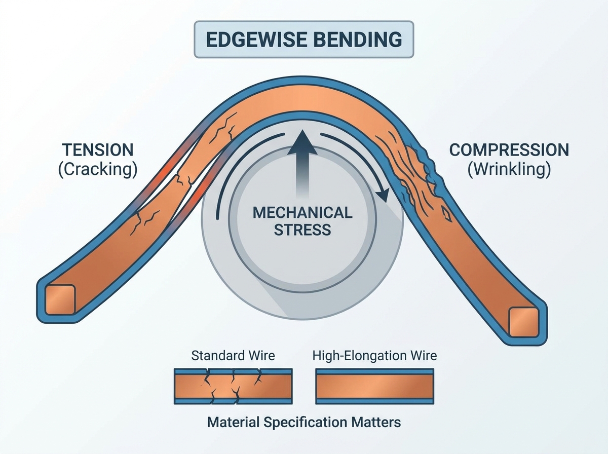
Mechanical Stress is Asymmetrical: Edgewise bending creates extreme elongation on the outer radius and severe compression on the inner radius, pushing enamel beyond its elastic limits.
Material Specification Matters: Standard insulation films often fail; success requires high-adhesion, high-elasticity coatings (like Polyamide-imide/PAI) and strictly controlled copper elongation properties.
Process Trumps Promises: Even premium wire will crack if tooling lacks proper radius tolerances, lubrication, or tension control during the winding process.
Total Cost of Quality: Upfront investments in specialized rectangular magnet wire and precision winding tooling offset the hidden costs of electrical shorts and field failures.
Understanding why insulation fails requires a close look at the physical forces at play. During an edgewise bend, the wire cross-section does not behave uniformly. The outer edge of the curve stretches significantly. We call this localized extreme tension. This stretching forces the protective enamel to thin out and eventually fracture because it exceeds its maximum elongation limit. Conversely, the inner edge undergoes severe compression. This compressive force causes the underlying copper to buckle inward. As the metal buckles, the enamel loses its grip, causing it to wrinkle or flake off entirely. The neutral axis remains near the center of the wire, but the extreme edges bear the destructive forces.
The aspect ratio of your conductor dictates the severity of this problem. We define the aspect ratio as the width of the wire divided by its thickness. A wire measuring 2mm by 4mm has a manageable aspect ratio of 2:1. However, a wire measuring 2mm by 10mm has a much higher aspect ratio of 5:1. Higher aspect ratios exponentially increase the applied stress during edgewise operations. The metal simply has more distance to stretch on the outside and compress on the inside. You must account for these geometry constraints before starting any high-volume production run.
Engineers rely on the R/t ratio to evaluate bend feasibility accurately. This industry-standard metric divides the inner bend radius (R) by the wire thickness (t). It provides a reliable baseline to predict potential failures. Pushing your design below a 1:1 or 2:1 ratio practically guarantees enameled flat wire bending cracks without specialized intervention. Most standard commercial wires fail long before they reach these tight dimensions. You must evaluate the R/t ratio early in the design phase to avoid unexpected manufacturing bottlenecks.
Your choice of raw material determines your success long before the wire touches a winding machine. Copper hardness directly impacts the conductor's yield strength. If the copper remains too hard due to inadequate annealing, it resists deformation. This resistance increases spring-back after the bending shoe releases the wire. High spring-back transfers excessive shear stress directly into the fragile insulation layer. You need dead-soft copper to absorb the mechanical deformation smoothly. When dealing with rectangular magnet wire edgewise bending, demanding strict elongation limits from your supplier prevents many downstream issues.
The chemical composition of your enamel plays an equally critical role. Standard polyurethane or polyester enamels work perfectly for gentle flatwise bends. However, they lack the molecular flexibility required for tight edgewise turns. Specialized high-temperature coatings, such as Polyamide-imide (PAI) overcoats, offer superior elasticity. Furthermore, the primer layer acts as the vital glue between the raw copper and the topcoat. If the primer fails to maintain adhesion during severe deformation, the topcoat will detach, regardless of its inherent flexibility. A highly engineered primer layer ensures the entire insulation system moves together as one cohesive unit.
Many engineers wrongly assume thicker insulation prevents cracking. This common misconception often leads to catastrophic failures. Thicker enamel builds actually prove more prone to shear stress fractures during tight edgewise bends. The outer surface of a thick coating sits further away from the wire's neutral axis. This increased distance magnifies the tensile strain on the outermost layer of the polymer. Instead of adding raw thickness, you should specify higher-grade resins applied in thinner, precisely controlled layers.
Even the highest-grade wire will fail if your equipment mistreats it. Inadequate tooling design ranks as a top contributor to insulation damage. Improper mandrel sizing creates irregular bending radii. A lack of lateral support allows the wire to twist slightly as it bends, introducing destructive torsional forces. Additionally, worn bending dies develop microscopically rough surfaces. These rough spots create micro-abrasions on the enamel surface. Under tension, these tiny scratches quickly propagate into full-scale enamel cracking during winding. You must inspect and polish your tooling surfaces regularly to maintain absolute smoothness.
Tension and winding speed also dictate the survival of your insulation. High-speed winding limits the material's ability to undergo plastic deformation smoothly. Metals and polymers need a fraction of a second to flow and adjust to new shapes. When you force the bend too rapidly, the enamel snaps instead of stretching. Dynamic tension control solves this problem. Servo-driven tensioners adjust the pulling force in real-time as the wire travels around the non-circular mandrel. This technology prevents sudden spikes in tension, protecting the fragile coating from intermittent shock loads.
Friction remains the silent enemy of enameled surfaces. Surface lubricants, such as paraffin wax or specialized synthetic oils, help the wire glide cleanly through the tooling. The finish of your guiding wheels and bending shoes also matters. High friction on the guiding tools physically grabs the enamel. As the machine pulls the copper forward, the stuck enamel stretches longitudinally. This stretching inevitably leads to severe rupture. Applying the correct lubrication reduces friction, lowers localized heat generation, and dramatically extends the life of both your tooling and your wire.
Solving this problem requires a systematic approach. You cannot simply guess which variable causes the failure. We break the solutions down into two distinct categories to help you prioritize your engineering efforts effectively.
Solution Category 1: Material Substitution. Start by evaluating your magnet wire suppliers. Do not accept generic commodity wire for demanding edgewise applications. Demand comprehensive material certificates from your vendors. These documents must detail the specific copper elongation percentage and the exact adherence test results. Ask for documentation proving the wire's specific suitability for tight-radius edgewise bending. If a supplier hesitates to provide these test results, you should look for a more capable partner.
Solution Category 2: Tooling and Machinery Upgrades. Sometimes the material is perfect, but the machine falls short. Consider upgrading to modern CNC edgewise winding machines. Evaluate key features before making a purchase. Look for servo-controlled tension systems to eliminate shock loads. Demand customized bending shoes designed specifically for your wire's exact aspect ratio. Finally, ensure the machine features automated spring-back compensation to prevent the wire from distorting after the bend completes.
You must acknowledge the implementation risks associated with these solutions. Changing wire suppliers might alter the thermal class of your coil. It may also change the finished dimensions, requiring a complete re-certification of your product. Upgrading your machinery requires operator retraining and meticulous tooling recalibration. Plan for these transition periods to avoid unexpected production delays.
You must frame this technical issue as a business problem to secure the necessary engineering budget. Compare the upfront cost of premium, application-specific wire against the daily losses on your factory floor. Calculate the monetary value of scrapped coils, manual rework hours, and compromised product warranties. Investing in advanced tooling or highly engineered polymers initially seems expensive. However, eliminating production bottlenecks and reducing field failure rates quickly justifies this initial spending.
Hold your suppliers accountable through rigorous testing protocols. Advise your procurement team to request sample prototype runs before signing bulk contracts. A trustworthy supplier should confidently provide cross-sectional analysis on the wire after the edgewise bend. They must also perform post-bend dielectric testing to prove the insulation maintains its integrity.
Table: Diagnostic Testing Protocols for Winding Insulation
Test Method | Primary Purpose | Detection Capability |
|---|---|---|
Salt Water Pinhole Test | Identifies micro-fractures in the enamel. | Detects invisible cracks that expose raw copper. |
High-Voltage Surge Test | Simulates operational electrical stress. | Reveals turn-to-turn short circuits caused by thin insulation. |
Dielectric Breakdown Test | Measures maximum voltage endurance. | Verifies if the bent enamel maintains its rated thermal and electrical class. |
Cross-Sectional Microscopy | Examines physical deformation post-bend. | Checks for inner-radius wrinkling and outer-radius thinning. |
As an actionable next step, audit your current winding parameters before you procure new wire. Record your exact operating speed, the calculated R/t ratio, and the applied tension limits. Ensure your winding machine is properly calibrated. Often, a simple adjustment to the dynamic tensioner or a fresh polish on a worn bending shoe resolves the issue without requiring a complete material overhaul.
Preventing wire fractures requires a precise match between the metallurgical limits of the copper, the elasticity of the enamel, and the exact geometry of the machine's tooling.
Do not rely solely on thicker insulation; instead, source flexible, high-adhesion topcoats like PAI paired with dead-soft copper.
Upgrade your production processes by implementing dynamic servo-tension control and proper surface lubrication to eliminate shock loads and destructive friction.
Encourage your engineering and procurement teams to collaborate closely, shifting your purchasing strategy away from cheap commodity wire toward application-specific material sourcing.
A: The minimum bend radius heavily depends on the wire's thickness and the specific enamel type. Generally, pushing the inner radius below 1.5 times the wire's width causes failure. Achieving tighter bends requires highly specialized dead-soft copper, high-elasticity coatings, and precision CNC tooling.
A: Thermal assistance can successfully soften certain enamels to improve temporary flexibility during the bend. However, it risks compromising the long-term thermal class of the polymer. Uncontrolled heating also causes severe over-thinning at the bend apex. You must strictly monitor the temperature if you use this method.
A: You cannot rely on visual inspections. Engineers use standard diagnostic methods like the salt water bath test to find exposed copper. High-voltage surge testing and dielectric breakdown tests also effectively expose compromised insulation integrity caused by microscopic fractures.