Views: 0 Author: Site Editor Publish Time: 2026-09-01 Origin: Site
Discovering a defect in a Continuously Transposed Conductor (CTC) after winding or curing leads to catastrophic rework costs. Project delays compound rapidly when failures happen late in the manufacturing cycle. You simply cannot afford to find inter-strand shorts once the active part enters the curing oven. Pre-winding inspection serves as the only reliable intervention point. It prevents hidden shorts and ensures you meet targeted eddy current loss reductions. Catching errors early protects your production schedule and maintains product reliability. This guide outlines a standardized protocol for electrical, mechanical, and visual evaluations. We will walk you through exact testing procedures and acceptance criteria. You will learn how to implement strict quality checks to secure your transformer manufacturing process from day one.
Proactive Defect Mitigation: Pre-winding CTC conductor inspection drastically reduces the risk of in-process transformer failures and scrap rates.
Electrical Verification: The CTC strand insulation test is non-negotiable for detecting microscopic enamel breaches caused during transposition or transit.
Dimensional & Mechanical Rigor: Strict adherence to transposition pitch and yield strength tolerances prevents winding deformation and hot spots.
Process Standardization: Integrating these steps into a formalized quality control framework ensures consistent, verifiable supplier evaluation and internal compliance.
Transformer manufacturers face a simple business reality. The cost of rigorous incoming inspection is negligible. Conversely, tearing down a failed active part destroys project profitability. If a transformer fails routine testing due to an internal CTC short, you must untank the unit. You must then unwind the coils and scrap expensive copper. You lose weeks of production time. Implementing a strict CTC conductor inspection protocol prevents these devastating scenarios.
Latent defects often originate during supplier manufacturing or transit. These hidden issues threaten transformer reliability. Slipped paper layers expose bare enamel to mechanical damage. Heavy impacts crush the enamel. Incorrect transposition pitch disrupts current sharing between strands. These defects rarely announce themselves visibly. You must hunt for them systematically.
You need clear success criteria to determine whether a CTC drum passes or fails. A passable drum must exhibit zero continuity between adjacent strands. Dimension variances must fall strictly within +/- 0.05mm of the engineering drawing. You should also demand flawless paper wrapping tension. Establishing these baseline pass/fail metrics eliminates guesswork on the shop floor.
Accepting drums based solely on supplier factory acceptance test (FAT) data.
Ignoring minor outer paper damage caused by forklift handling.
Failing to document dimensional measurements for traceability.
Visual and dimensional checks form the first line of defense. You must measure the overall axial and radial dimensions of the bundled conductor over the insulation. These measurements confirm the conductor will fit inside the calculated winding window. Oversized CTC causes severe radial build issues during winding. Undersized CTC risks mechanical instability during short circuits.
Insulation integrity requires meticulous scrutiny. Inspect the outer Kraft paper or polyester netting. Look for tears, loose wrapping, or improper tensioning. Poorly tensioned paper unravels under winding tension. This unraveling leads to insulation voids and potential dielectric failure. Your technicians must rotate the drum and visually inspect the exposed outer layer thoroughly.
Transposition pitch verification guarantees optimal current sharing. You must confirm the length of one complete transposition cycle aligns with design specifications. Incorrect pitch fails to cancel magnetic flux linkages. This failure generates circulating currents and localized thermal hot spots. Measure several pitch lengths and calculate the average to verify supplier consistency.
Visual checks alone are insufficient. The enameled strands remain hidden beneath paper or netting. You cannot see micro-cracks in the enamel. You cannot see internal burrs cutting through the insulation. Recognizing this implementation reality pushes you to follow visual checks immediately with rigorous electrical tests.
Use calibrated digital micrometers with flat anvils.
Measure dimensions at three distinct points along the first meter of the conductor.
Compare measurements directly against the specific winding design data, not just standard catalog tolerances.
Table 1: Visual and Dimensional Inspection Checklist
Inspection Item | Methodology | Acceptance Criteria |
|---|---|---|
Axial/Radial Dimensions | Digital micrometer at 3 locations | Within +/- 0.05mm of specification |
Outer Insulation | Visual scan of drum surface | No tears, tight wrapping, no slipped layers |
Transposition Pitch | Measure 5 consecutive pitches, average | Matches design specification +/- 2% |
Surface Cleanliness | Visual scan and wipe test | Free from moisture, oil, and metallic dust |
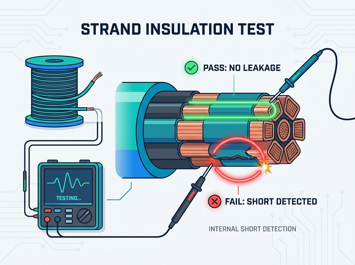
The core purpose of electrical testing is identifying internal shorts. You must detect breaches between individual rectangular enameled copper strands. These shorts bypass visual detection completely. If left unchecked, they create circulating currents. These currents generate excessive heat, degrading the surrounding paper insulation and eventually causing a major dielectric fault.
You need specific apparatus for this evaluation. Technicians rely on a low-voltage insulation resistance tester, commonly known as a Megger. You apply this tester to the exposed ends of the CTC spool. A 500V DC test voltage typically suffices for standard enamel thicknesses. Higher voltages risk puncturing otherwise healthy enamel.
Strip the ends carefully: Remove outer paper without nicking the enamel. Use chemical strippers or specialized rotary brushes. Never use sharp utility knives, as they induce the exact mechanical damage you want to test for.
Separate the strands: Fan out the individual copper strands to ensure they do not touch each other at the exposed ends.
Test adjacent strands: Measure resistance between every adjacent strand in the bundle (e.g., Strand 1 to 2, 2 to 3, 3 to 4).
Test alternating combinations: Test resistance between alternating strands, and finally, test each individual strand against the rest of the bundled strands tied together.
You must define strict acceptance thresholds. Minimum acceptable Megohm values depend on industry norms. IEC and IEEE guidelines for enamel insulation provide excellent baselines. Many manufacturers set a minimum threshold of 500 Megohms at 500V DC. If a strand combination reads below this limit, it flags a potential enamel breach. Executing a proper CTC strand insulation test ensures only healthy copper reaches your winding machines.
Troubleshooting test results requires experience. You must learn to isolate false positives. Moisture ingress at the exposed spool ends often creates tracking paths. These paths mimic an internal insulation failure. If you read low resistance, try drying the exposed ends with a hot air gun. Retest after drying. If the resistance jumps back above 500 Megohms, moisture caused the issue. If it remains low, you have a true internal short.
Winding presents distinct mechanical realities. CTC must act stiff enough to maintain structural integrity under severe short-circuit forces. Simultaneously, it must remain flexible enough to bend around the winding mandrel without cracking the enamel. Balancing these competing requirements defines a high-quality conductor.
Spring-back testing measures the conductor's tendency to return to its original shape after bending. You bend a sample piece around a standardized radius. You then release it and measure the angle of recovery. High spring-back makes winding difficult. It forces winders to over-bend the copper, stressing the internal strands. Low spring-back ensures the conductor holds the necessary radii at the corners of rectangular windings.
You must verify enamel adhesion under stress. Bending creates tension on the outer radius and compression on the inner radius. Visually inspect the inner radius of a test bend. Look for micro-cracking in the enamel. Check for localized crushing of the paper insulation. Flaking enamel indicates poor varnish curing during the supplier's manufacturing process. This flaking will inevitably cause inter-strand shorts during winding.
Use mechanical consistency as a primary metric when evaluating suppliers. Track 0.2% proof stress values across different deliveries. Some designs require hardened copper (e.g., CPR1, CPR2) to withstand high radial forces. If a supplier sends dead-soft copper when you specified hardened, your transformer will collapse during a short-circuit fault.
Table 2: Mechanical Performance Chart
Mechanical Property | Testing Method | Potential Winding Impact |
|---|---|---|
0.2% Proof Stress (Yield) | Tensile testing machine | Determines short-circuit withstand capability |
Spring-Back Angle | Standardized mandrel bend test | Affects corner radii accuracy during winding |
Enamel Adhesion | Visual inspection post-bending | Prevents flaking and subsequent electrical shorts |
Transitioning from ad-hoc checks to a mandated protocol transforms your production floor. You must build a documented QA checklist for every incoming drum. Relying on technician memory guarantees inconsistencies. Create digital forms that force inspectors to log specific values before releasing the material. Effective continuously transposed conductor quality control removes subjectivity from the receiving bay.
Data logging and traceability protect your liability. You must tie specific drum inspection results to specific transformer serial numbers. Record the insulation resistance values. Log the dimensional variances. If a transformer fails in the field five years later, you can trace the exact copper batch. This traceability helps you identify systemic supplier issues over time.
Leverage aggregated inspection data for supplier accountability. If you notice a slow upward drift in dimensional variances, challenge the supplier. Require them to submit factory acceptance test (FAT) data prior to shipment. Compare their FAT data against your incoming inspection data. Significant discrepancies indicate poor supplier calibration or transit damage. Hold them financially accountable for rejected drums.
Address the operational friction of adoption. Adding time to the receiving process frustrates logistics teams. You must train technicians for efficient, repeatable testing. Provide them with dedicated testing stations. Equip them with specialized stripping tools and pre-configured Meggers. When you remove bottlenecks, compliance increases naturally.
Time constraints: Dedicate specific personnel to inspection rather than burdening forklift drivers.
Skill gaps: Implement weekly training sessions on identifying moisture-induced false positives.
Tool availability: Maintain calibrated backup tools to prevent workflow halts when a primary Megger requires calibration.
Skipping pre-winding inspections creates unacceptable financial and reputational risks for transformer manufacturers. Discovering a shorted strand during active part testing ruins production schedules and consumes massive rework budgets. You protect your margins by catching defects in the receiving bay.
Standardize your electrical and dimensional checks immediately. Make these tests mandatory gating procedures before releasing materials to the winding floor. Do not allow production pressure to bypass quality control. A disciplined approach ensures only verified, healthy copper goes into your transformers.
Take action today. Audit your current incoming material inspection checklists. Upgrade your diagnostic tools, ensuring you have calibrated digital micrometers and reliable insulation testers. Train your team to perform accurate strand-to-strand measurements. Securing your supply chain at the receiving door guarantees long-term transformer reliability.
A: Manufacturing burrs and excessive transposition pressure are frequent culprits. Impact damage during shipping also plays a major role. These mechanical forces crush or slice through the thin enamel coating, creating direct copper-to-copper shorts between adjacent strands hidden under the outer paper.
A: Localized outer damage can sometimes be carefully re-taped if the enamel remains intact. However, internal strand-to-strand shorts generally require rejecting the affected section. If the short runs deep into the spool, you must reject the entire drum to prevent winding compromised material.
A: Transposition pitch equalizes the length and position of each strand within the magnetic field. Incorrect pitch fails to properly cancel out magnetic flux linkages. This failure leads to increased circulating currents between strands, drastically raising eddy current losses and generating dangerous thermal hot spots.
A: You need precision digital calipers or micrometers for accurate dimensional verification. A calibrated low-voltage insulation resistance tester (Megger) is mandatory for electrical checks. Finally, mechanical bend-test fixtures and specialized chemical or mechanical enamel strippers round out a complete inspection toolkit.